7 IP version 4
There are multiple LAN protocols below the IP layer and multiple transport protocols above, but IP itself stands alone. The Internet is essentially the IP Internet. If you want to run your own LAN somewhere or if you want to run your own transport protocol, the Internet backbone will still work for you. But if you want to change the IP layer, you may encounter difficulty. (Just talk to the IPv6 people, or the IP-multicasting or IP-reservations groups.)
IP is, in effect, a universal routing and addressing protocol. The two are developed together; every node has an IP address and every router knows how to handle IP addresses. IP was originally seen as a way to interconnect multiple LANs, but it may make more sense now to view IP as a virtual LAN overlaying all the physical LANs.
A crucial aspect of IP is its scalability. As the Internet has grown to ~109 hosts, the forwarding tables are not much larger than 105 (perhaps now 105.5). Ethernet, in comparison, scales poorly.
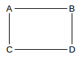
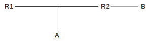
Furthermore, IP, unlike Ethernet, offers excellent support for multiple redundant links. If the network below were an IP network, each node would communicate with each immediate neighbor via their shared direct link. If, on the other hand, this were an Ethernet network with the spanning-tree algorithm, then one of the four links would simply be disabled completely.
The IP network service model is to act like a LAN. That is, there are no acknowledgments; delivery is generally described as best-effort. This design choice is perhaps surprising, but it has also been quite fruitful.
Currently the Internet uses (almost exclusively) IP version 4, with its 32-bit address size. As the Internet has run out of new large blocks of IPv4 addresses (1.10 IP - Internet Protocol), there is increasing pressure to convert to IPv6, with its 128-bit address size. Progress has been slow, however, and delaying tactics such as IPv4-address markets and NAT have allowed IPv4 to continue. Aside from the major change in address structure, there are relatively few differences in the routing models of IPv4 and IPv6. We will study IPv4 in this chapter and IPv6 in the following.
If you want to provide a universal service for delivering any packet anywhere, what else do you need besides routing and addressing? Every network (LAN) needs to be able to carry any packet. The protocols spell out the use of octets (bytes), so the only possible compatibility issue is that a packet is too large for a given network. IP handles this by supporting fragmentation: a network may break a too-large packet up into units it can transport successfully. While IP fragmentation is inefficient and clumsy, it does guarantee that any packet can potentially be delivered to any node.
7.1 The IPv4 Header
The IPv4 Header needs to contain the following information:
- destination and source addresses
- indication of ipv4 versus ipv6
- a Time To Live (TTL) value, to prevent infinite routing loops
- a field indicating what comes next in the packet (eg TCP v UDP)
- fields supporting fragmentation and reassembly.
Here is how it is all laid out in the header. Each row is 32 bits wide.
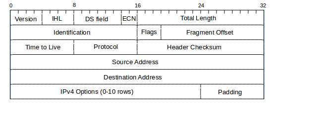
The IP header, and basics of IP protocol operation, were defined in RFC 791; some minor changes have since occurred. Most of these changes were documented in RFC 1122, though the DS field was defined in RFC 2474 and the ECN bits were first proposed in RFC 2481.
The Version field is, for IPv4, the number 4: 0100. The IHL field represents the total IP Header Length, in 32-bit words; an IP header can thus be at most 15 words long. The base header takes up five words, so the IP Options can consist of at most ten words. If one looks at IPv4 packets using a packet-capture tool that displays the packets in hex, the first byte will most often be 0x45.
The Differentiated Services (DS) field is used by the Differentiated Services suite to specify preferential handling for designated packets, eg those involved in VoIP or other real-time protocols. The Explicit Congestion Notification bits are there to allow routers experiencing congestion to mark packets, thus indicating to the sender that the transmission rate should be reduced. We will address these in 14.8.2 Explicit Congestion Notification (ECN). These two fields together replace the old 8-bit Type of Service field.
The Total Length field is present because an IP packet may be smaller than the minimum LAN packet size (see Exercise 1) or larger than the maximum (if the IP packet has been fragmented over several LAN packets. The IP packet length, in other words, cannot be inferred from the LAN-level packet size. Because the Total Length field is 16 bits, the maximum IP packet size is 216 bytes. This is probably much too large, even if fragmentation were not something to be avoided.
The second word of the header is devoted to fragmentation, discussed below.
The Time-to-Live (TTL) field is decremented by 1 at each router; if it reaches 0, the packet is discarded. A typical initial value is 64; it must be larger than the total number of hops in the path. In most cases, a value of 32 would work. The TTL field is there to prevent routing loops – always a serious problem should they occur – from consuming resources indefinitely. Later we will look at various IP routing-table update protocols and how they minimize the risk of routing loops; they do not, however, eliminate it. By comparison, Ethernet headers have no TTL field, but Ethernet also disallows cycles in the underlying topology.
The Protocol field contains a value to indicate if the body of the IP packet represents a TCP packet or a UDP packet, or, in unusual cases, something else altogether.
The Header Checksum field is the “Internet checksum” applied to the header only, not the body. Its only purpose is to allow the discarding of packets with corrupted headers. When the TTL value is decremented the router must update the header checksum. This can be done “algebraically” by adding a 1 in the correct place to compensate, but it is not hard simply to re-sum the 8 halfwords of the average header.
The Source and Destination Address fields contain, of course, the IP addresses. These would be updated only by NAT firewalls.
One option is the Record Route option, in which routers are to insert their own IP address into the IP header option area. Unfortunately, with only ten words available, there is not enough space to record most longer routes (but see 7.9.1 Traceroute and Time Exceeded, below). Another option, now deprecated as security risk, is to support source routing. The sender would insert into the IP header option area a list of IP addresses; the packet would be routed to pass through each of those IP addresses in turn. With strict source routing, the IP addresses had to represent adjacent neighbors; no router could be used if its IP address were not on the list. With loose source routing, the listed addresses did not have to represent adjacent neighbors and ordinary IP routing was used to get from one listed IP address to the next. Both forms are essentially never used, again for security reasons: if a packet has been source-routed, it may have been routed outside of the at-least-somewhat trusted zone of the Internet backbone.
7.2 Interfaces
IP addresses (IPv4 and IPv6) are, strictly speaking, assigned not to hosts or nodes, but to interfaces. In the most common case, where each node has a single LAN interface, this is a distinction without a difference. In a room full of workstations each with a single Ethernet interface eth0 (or perhaps Ethernet adapter Local Area Connection), we might as well view the IP address assigned to the interface as assigned to the workstation itself.
Each of those workstations, however, likely also has a loopback interface (at least conceptually), providing a way to deliver IP packets to other processes on the same machine. On many systems, the name “localhost” resolves to the IPv4 address 127.0.0.1 (although the IPv6 address ::1 is also used). Delivering packets to the localhost address is simply a form of interprocess communication; a functionally similar alternative is named pipes. Loopback delivery avoids the need to use the LAN at all, or even the need to have a LAN. For simple client/server testing, it is often convenient to have both client and server on the same machine, in which case the loopback interface is convenient and fast. On unix-based machines the loopback interface represents a genuine logical interface, commonly named lo. On Windows systems the “interface” may not represent an actual entity, but this is of practical concern only to those interested in “sniffing” all loopback traffic; packets sent to the loopback address are still delivered as expected.
Workstations often have special other interfaces as well. Most recent versions of Microsoft Windows have a Teredo Tunneling pseudo-interface and an Automatic Tunneling pseudo-interface; these are both intended (when activated) to support IPv6 connectivity when the local ISP supports only IPv4. The Teredo protocol is documented in RFC 4380.
When VPN connections are created, as in 3.1 Virtual Private Network, each end of the logical connection typically terminates at a virtual interface (one of these is labeled tun0 in the diagram of 3.1 Virtual Private Network). These virtual interfaces appear, to the systems involved, to be attached to a point-to-point link that leads to the other end.
When a computer hosts a virtual machine, there is almost always a virtual network to connect the host and virtual systems. The host will have a virtual interface to connect to the virtual network. The host may act as a NAT router for the virtual machine, “hiding” that virtual machine behind its own IP address, or it may act as an Ethernet switch, in which case the virtual machine will need an additional public IP address.
Many workstations have both an Ethernet interface and a Wi-Fi interface. Both of these can be used simultaneously (with different IP addresses assigned to each), either on the same IP network or on different IP networks.
Routers always have at least two interfaces on two separate LANs. Generally this means a separate IP address for each interface, though some point-to-point interfaces can be used without being assigned an IP address (7.10 Unnumbered Interfaces).
Finally, it is usually possible to assign multiple IP addresses to a single interface. Sometimes this is done to allow two IP networks to share a single LAN; the interface might be assigned one IP address for each IP network. Other times a single interface is assigned multiple IP addresses that are on the same LAN; this is often done so that one physical machine can act as a server (eg a web server) for multiple distinct IP addresses corresponding to multiple distinct domain names.
While it is important to be at least vaguely aware of all these special cases, we emphasize again that in most ordinary contexts each end-user workstation has one IP address that corresponds to a LAN connection.
7.3 Special Addresses
A few IP addresses represent special cases.
While the standard IPv4 loopback address is 127.0.0.1, any IP address beginning with 127 can serve as a loopback address. Logically they all represent the current host. Most hosts are configured to resolve the name “localhost” to 127.0.0.1. However, any loopback address – eg. 127.255.33.57 – should work, eg with ping.
Private addresses are IP addresses intended only for site internal use, eg either behind a NAT firewall or intended to have no Internet connectivity at all. If a packet shows up at any non-private router (eg at an ISP router), with a private IP address as either source or destination address, the packet should be dropped. Three standard private-address blocks have been defined:
- 10.0.0.0/8
- 172.16.0.0/12
- 192.168.0.0/16
The last block is the one from which addresses are most commonly allocated by DHCP servers (7.8.1 DHCP and the Small Office) built into NAT routers.
Broadcast addresses are a special form of IP address intended to be used in conjunction with LAN-layer broadcast. The most common forms are “broadcast to this network”, consisting of all 1-bits, and “broadcast to network D”, consisting of D’s network-address bits followed by all 1-bits for the host bits. If you try to send a packet to the broadcast address of a remote network D, the odds are that some router involved will refuse to forward it, and the odds are even higher that, once the packet arrives at a router actually on network D, that router will refuse to broadcast it. Even addressing a broadcast to ones own network will fail if the underlying LAN does not support LAN-level broadcast (eg ATM).
The highly influential early Unix implementation Berkeley 4.2 BSD used 0-bits for the broadcast bits, instead of 1’s. As a result, to this day host bits cannot be all 1-bits or all 0-bits in order to avoid confusion with the IP broadcast address. One consequence of this is that a Class C network has 254 usable host addresses, not 256.
7.3.1 Multicast addresses
Finally, IP multicast addresses remain as the last remnant of the Class A/B/C strategy: multicast addresses are Class D, with first byte beginning 1110 (meaning that the first byte is, in decimal, 224-239). Multicasting means delivering to a specified set of addresses, preferably by some mechanism more efficient than sending to each address individually. A reasonable goal of multicast would be that no more than one copy of the multicast packet traverses any given link.
Support for IP multicast requires considerable participation by the backbone routers involved. For example, if hosts A, B and C each connect to different interfaces of router R1, and A wishes to send a multicast packet to B and C, then it is up to R1 to receive the packet, figure out that B and C are the intended recipients, and forward the packet twice, once for B’s interface and once for C’s. R1 must also keep track of what hosts have joined the multicast group and what hosts have left. Due to this degree of router participation, backbone router support for multicasting has not been entirely forthcoming. A discussion of IP multicasting appears in 18 Quality of Service.
7.4 Fragmentation
If you are trying to interconnect two LANs (as IP does), what else might be needed besides Routing and Addressing? IP explicitly assumes all packets are composed on 8-bit bytes (something not universally true in the early days of IP; to this day the RFCs refer to “octets” to emphasize this requirement). IP also defines bit-order within a byte, and it is left to the networking hardware to translate properly. Neither byte size nor bit order, therefore, can interfere with packet forwarding.
There is one more feature IP must provide, however, if the goal is universal connectivity: it must accommodate networks for which the maximum packet size, or Maximum Transfer Unit, MTU, is smaller than the packet that needs forwarding. Otherwise, if we were using IP to join Token Ring (MTU = 4KB, at least originally) to Ethernet (MTU = 1500B), the token-ring packets might be too large to deliver to the Ethernet side, or to traverse an Ethernet backbone en route to another Token Ring. (Token Ring, in its day, did commonly offer a configuration option to allow Ethernet interoperability.)
So, IP must support fragmentation, and thus also reassembly. There are two major strategies here: per-link fragmentation and reassembly, where the reassembly is done at the opposite end of the link (as in ATM), and path fragmentation and reassembly, where reassembly is done at the far end of the path. The latter approach is what is taken by IP, partly because intermediate routers are too busy to do reassembly (this is as true today as it was thirty years ago), and partly because IP fragmentation is seen as the strategy of last resort.
An IP sender is supposed to use a different value for the IDENT field for different packets, at least up until the field wraps around. When an IP datagram is fragmented, the fragments keep the same IDENT field, so this field in effect indicates which fragments belong to the same packet.
After fragmentation, the Fragment Offset field marks the start position of the data portion of this fragment within the data portion of the original IP packet. Note that the start position can be a number up to 216, the maximum IP packet length, but the FragOffset field has only 13 bits. This is handled by requiring the data portions of fragments to have sizes a multiple of 8 (three bits), and left-shifting the FragOffset value by 3 bits before using it.
As an example, consider the following network, where MTUs are excluding the LAN header:

Suppose A addresses a packet of 1500 bytes to B, and sends it via the LAN to the first router R1. The packet contains 20 bytes of IP header and 1480 of data.
R1 fragments the original packet into two packets of sizes 20+976 = 996 and 20+504=544. Having 980 bytes of payload in the first fragment would fit, but violates the rule that the sizes of the data portions be divisible by 8. The first fragment packet has FragOffset = 0; the second has FragOffset = 976.
R2 refragments the first fragment into three packets as follows:
- first: size = 20+376=396, FragOffset = 0
- second: size = 20+376=396, FragOffset = 376
- third: size = 20+224 = 244 (note 376+376+224=976), FragOffset = 752.
R2 refragments the second fragment into two:
- first: size = 20+376 = 396, FragOffset = 976+0 = 976
- second: size = 20+128 = 148, FragOffset = 976+376=1352
R3 then sends the fragments on to B, without reassembly.
Note that it would have been slightly more efficient to have fragmented into four fragments of sizes 376, 376, 376, and 352 in the beginning. Note also that the packet format is designed to handle fragments of different sizes easily. The algorithm is based on multiple fragmentation with reassembly only at the final destination.
Each fragment has its IP-header Total Length field set to the length of that fragment.
We have not yet discussed the three flag bits. The first bit is reserved, and must be 0. The second bit is the “Don’t Fragment” bit. If it is set to 1 by the sender then a router must not fragment the packet and must drop it instead; see 12.12 Path MTU Discovery for an application of this. The third bit is set to 1 for all fragments except the final one (this bit is thus set to 0 if no fragmentation has occurred). The third bit tells the receiver where the fragments stop.
The receiver must take the arriving fragments and reassemble them into a whole packet. The fragments may not arrive in order – unlike in ATM networks – and may have unrelated packets interspersed. The reassembler must identify when different arriving packets are fragments of the same original, and must figure out how to reassemble the fragments in the correct order; both these problems were essentially trivial for ATM.
Fragments are considered to belong to the same packet if they have the same IDENT field and also the same source and destination addresses and same protocol.
As all fragment sizes are a multiple of 8 bytes, the receiver can keep track of whether all fragments have been received with a bitmap in which each bit represents one 8-byte fragment chunk. A 1 KB packet could have up to 128 such chunks; the bitmap would thus be 16 bytes.
If a fragment arrives that is part of a new (and fragmented) packet, a buffer is allocated. While the receiver cannot know the final size of the buffer, it can usually make a reasonable guess. Because of the FragOffset field, the fragment can then be stored in the buffer in the appropriate position. A new bitmap is also allocated, and a reassembly timer is started.
As subsequent fragments arrive, not necessarily in order, they too can be placed in the proper buffer in the proper position, and the appropriate bits in the bitmap are set to 1.
If the bitmap shows that all fragments have arrived, the packet is sent on up as a completed IP packet. If, on the other hand, the reassembly timer expires, then all the pieces received so far are discarded.
TCP connections usually engage in Path MTU Discovery, and figure out the largest packet size they can send that will not entail fragmentation (12.12 Path MTU Discovery). But it is not unusual, for example, for UDP protocols to use fragmentation, especially over the short haul. In the Network File Sharing (NFS) protocol, for example, UDP is used to carry 8KB disk blocks. These are often sent as a single 8+ KB IP packet, fragmented over Ethernet to five full packets and a fraction. Fragmentation works reasonably well here because most of the time the packets do not leave the Ethernet they started on. Note that this is an example of fragmentation done by the sender, not by an intermediate router.
Finally, any given IP link may provide its own link-layer fragmentation and reassembly; we saw in 3.8.1 ATM Segmentation and Reassembly that ATM does just this. Such link-layer mechanisms are, however, generally invisible to the IP layer.
7.5 The Classless IP Delivery Algorithm
Recall from Chapter 1 that any IP address can be divided into a net portion IPnet and a host portion IPhost; the division point was determined by whether the IP address was a Class A, a Class B, or a Class C. We also hinted in Chapter 1 that the division point was not always so clear-cut; we now present the delivery algorithm, for both hosts and routers, that does not assume a globally predeclared division point of the input IP address into net and host portions. We will, for the time being, punt on the question of forwarding-table lookup and assume there is a lookup() method available that, when given a destination address, returns the next_hop neighbor.
Instead of class-based divisions, we will assume that each of the IP addresses assigned to a node’s interfaces is configured with an associated length of the network prefix; following the slash notation of 1.10 IP - Internet Protocol, if B is an address and the prefix length is k = kB then the prefix itself is B/k. As usual, an ordinary host may have only one IP interface, while a router will always have multiple interfaces.
Let D be the given IP destination address; we want to decide if D is local or nonlocal. The host or router involved may have multiple IP interfaces, but for each interface the length of the network portion of the address will be known. For each network address B/k assigned to one of the host’s interfaces, we compare the first k bits of B and D; that is, we ask if D matches B/k.
- If one of these comparisons yields a match, delivery is local; the host delivers the packet to its final destination via the LAN connected to the corresponding interface. This means looking up the LAN address of the destination, if applicable, and sending the packet to that destination via the interface.
- If there is no match, delivery is nonlocal, and the host passes D to the lookup() routine of the forwarding table and sends to the associated next_hop (which must represent a physically connected neighbor). It is now up to lookup() routine to make any necessary determinations as to how D might be split into Dnet and Dhost.
The forwarding table is, abstractly, a set of network addresses – now also with lengths – each of the form B/k, with an associated next_hop destination for each. The lookup() routine will, in principle, compare D with each table entry B/k, looking for a match (that is, equality of the first k bits). As with the interfaces check above, the net/host division point (that is, k) will come from the table entry; it will not be inferred from D or from any other information borne by the packet. There is, in fact, no place in the IP header to store a net/host division point, and furthermore different routers along the path may use different values of k with the same destination address D. In 10 Large-Scale IP Routing we will see that in some cases multiple matches in the forwarding table may exist; the longest-match rule will be introduced to pick the best match.
The forwarding table may also contain a default entry for the next_hop, which it may return in cases when the destination D does not match any known network. We take the view here that returning such a default entry is a valid result of the routing-table lookup() operation, rather than a third option to the algorithm above; one approach is for the default entry to be the network address 0.0.0.0/0, which does indeed match everything (use of this would definitely require the above longest-match rule, though).
Default routes are hugely important in keeping leaf forwarding tables small. Even backbone routers sometimes expend considerable effort to keep the network address prefixes in their forwarding tables as short as possible, through consolidation.
Routers may also be configured to allow passing quality-of-service information to the lookup() method, as mentioned in Chapter 1, to support different routing paths for different kinds of traffic (eg bulk file-transfer versus real-time).
For a modest exception to the local-delivery rule described here, see below in 7.10 Unnumbered Interfaces.
7.6 IP Subnets
Subnets were the first step away from Class A/B/C routing: a large network (eg a class A or B) could be divided into smaller IP networks called subnets. Consider, for example, a typical Class B network such as Loyola University’s (originally 147.126.0.0/16); the underlying assumption is that any packet can be delivered via the underlying LAN to any internal host. This would require a rather large LAN, and would require that a single physical LAN be used throughout the site. What if our site has more than one physical LAN? Or is really too big for one physical LAN? It did not take long for the IP world to run into this problem.
Subnets were first proposed in RFC 917, and became official with RFC 950.
Getting a separate IP network prefix for each subnet is bad for routers: the backbone forwarding tables now must have an entry for every subnet instead of just for every site. What is needed is a way for a site to appear to the outside world as a single IP network, but for further IP-layer routing to be supported inside the site. This is what subnets accomplish.
Subnets introduce hierarchical routing: first we route to the primary network, then inside that site we route to the subnet, and finally the last hop delivers to the host.
Routing with subnets involves in effect moving the IPnet division line rightward. (Later, when we consider CIDR, we will see the complementary case of moving the division line to the left.) For now, observe that moving the line rightward within a site does not affect the outside world at all; outside routers are not even aware of site-internal subnetting.
In the following diagram, the outside world directs traffic addressed to 147.126.0.0/16 to the router R. Internally, however, the site is divided into subnets. The idea is that traffic from 147.126.1.0/24 to 147.126.2.0/24 is routed, not switched; the two LANs involved may not even be compatible. Most of the subnets shown are of size /24, meaning that the third byte of the IP address has become part of the network portion of the subnet’s address; one /20 subnet is also shown. RFC 950 would have disallowed the subnet with third byte 0, but having 0 for the subnet bits generally does work.
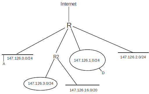
What we want is for the internal routing to be based on the extended network prefixes shown, while externally continuing to use only the single routing entry for 147.126.0.0/16.
To implement subnets, we divide the site’s IP network into some combination of physical LANs – the subnets –, and assign each a subnet address: an IP network address which has the site’s IP network address as prefix. To put this more concretely, suppose the site’s IP network address is A, and consists of n network bits (so the site address may be written with the slash notation as A/n); in the diagram above, A/n = 147.126.0.0/16. A subnet address is an IP network address B/k such that:
- The address B/k is within the site: the first n bits of B are the same as A/n’s
- B/k extends A/n: k≥n
An example B/k in the diagram above is 147.126.1.0/24. (There is a slight simplification here in that subnet addresses do not absolutely have to be prefixes; see below.)
We now have to figure out how packets will be routed to the correct subnet. For incoming packets we could set up some proprietary protocol at the entry router to handle this. However, the more complicated situation is all those existing internal hosts that, under the class A/B/C strategy, would still believe they can deliver via the LAN to any site host, when in fact they can now only do that for hosts on their own subnet. We need a more general solution.
We proceed as follows. For each subnet address B/k, we create a subnet mask for B consisting of k 1-bits followed by enough 0-bits to make a total of 32. We then make sure that every host and router in the site knows the subnet mask for every one of its interfaces. Hosts usually find their subnet mask the same way they find their IP address (by static configuration if necessary, but more likely via DHCP, below).
Hosts and routers now apply the IP delivery algorithm of the previous section, with the proviso that, if a subnet mask for an interface is present, then the subnet mask is used to determine the number of address bits rather than the Class A/B/C mechanism. That is, we determine whether a packet addressed to destination D is deliverable locally via an interface with subnet address B/k and corresponding mask M by comparing D&M with B&M, where & represents bitwise AND; if the two match, the packet is local. This will generally involve a match of more bits than if we used the Class A/B/C strategy to determine the network portion of addresses D and B.
As stated previously, given an address D with no other context, we will not be able to determine the network/host division point in general (eg for outbound packets). However, that division point is not in fact what we need. All that is needed is a way to tell if a given destination host address D belongs to the current subnet, say B; that is, we need to compare the first k bits of D and B where k is the (known) length of B.
In the diagram above, the subnet mask for the /24 subnets would be 255.255.255.0; bitwise ANDing any IP address with the mask is the same as extracting the first 24 bits of the IP address, that is, the subnet portion. The mask for the /20 subnet would be 255.255.240.0 (240 in binary is 1111 0000).
In the diagram above none of the subnets overlaps or conflicts: the subnets 147.126.0.0/24 and 147.126.1.0/24 are disjoint. It takes a little more effort to realize that 147.126.16.0/20 does not overlap with the others, but note that an IP address matches this network prefix only if the first four bits of the third byte are 0001, so the third byte itself ranges from decimal 32 to decimal 63 = binary 0001 1111.
Note also that if host A = 147.126.0.1 wishes to send to destination D = 147.126.1.1, and A is not subnet-aware, then delivery will fail: A will infer that the interface is a Class B, and therefore compare the first two bytes of A and D, and, finding a match, will attempt direct LAN delivery. But direct delivery is now likely impossible, as the subnets are not joined by a switch. Only with the subnet mask will A realize that its network is 147.126.0.0/24 while D’s is 147.126.1.0/24 and that these are not the same. A would still be able to send packets to its own subnet. In fact A would still be able to send packets to the outside world: it would realize that the destination in that case does not match 147.126.0.0/16 and will thus forward to its router. Hosts on other subnets would be the only unreachable ones.
Properly, the subnet address is the entire prefix, eg 147.126.65.0/24. However, it is often convenient to identify the subnet address with just those bits that represent the extension of the site IP-network address; we might thus say casually that the subnet address here is 65.
The class-based IP-address strategy allowed any host anywhere on the Internet to properly separate any address into its net and host portions. With subnets, this division point is now allowed to vary; for example, the address 147.126.65.48 divides into 147.126 | 65.48 outside of Loyola, but into 147.126.65 | 48 inside. This means that the net-host division is no longer an absolute property of addresses, but rather something that depends on where the packet is on its journey.
Technically, we also need the requirement that given any two subnet addresses of different, disjoint subnets, neither is a proper prefix of the other. This guarantees that if A is an IP address and B is a subnet address with mask M (so B = B&M), then A&M = B implies A does not match any other subnet. Regardless of the net/host division rules, we cannot possibly allow subnet 147.126.16.0/20 to represent one LAN while 147.126.16.0/24 represents another; the second subnet address block is a subset of the first. (We can, and sometimes do, allow the first LAN to correspond to everything in 147.126.16.0/20 that is not also in 147.126.16.0/24; this is the longest-match rule.)
The strategy above is actually a slight simplification of what the subnet mechanism actually allows: subnet address bits do not in fact have to be contiguous, and masks do not have to be a series of 1-bits followed by 0-bits. The mask can be any bit-mask; the subnet address bits are by definition those where there is a 1 in the mask bits. For example, we could at a Class-B site use the fourth byte as the subnet address, and the third byte as the host address. The subnet mask would then be 255.255.0.255. While this generality was once sometimes useful in dealing with “legacy” IP addresses that could not easily be changed, life is simpler when the subnet bits precede the host bits.
7.6.1 Subnet Example
As an example of having different subnet masks on different interfaces, let us consider the division of a class-C network into subnets of size 70, 40, 25, and 20. The subnet addresses will of necessity have different lengths, as there is not room for four subnets each able to hold 70 hosts.
- A: size 70
- B: size 40
- C: size 25
- D: size 20
Because of the different subnet-address lengths, division of a local IP address LA into net versus host on subnets cannot be done in isolation, without looking at the host bits. However, that division is not in fact what we need. All that is needed is a way to tell if the local address LA belongs to a given subnet, say B; that is, we need to compare the first n bits of LA and B, where n is the length of B’s subnet mask. We do this by comparing LA&M to B&M, where M is the mask corresponding to n. LA&M is not necessarily the same as LAnet, if LA actually belongs to one of the other subnets. However, if LA&M = B&M, then LA must belong subnet B, in which case LA&M is in fact LAnet.
We will assume that the site’s IP network address is 200.0.0.0/24. The first three bytes of each subnet address must match 200.0.0. Only some of the bits of the fourth byte will be part of the subnet address, so we will switch to binary for the last byte, and use both the /n notation (for total number of subnet bits) and also add a vertical bar | to mark the separation between subnet and host.
Example: 200.0.0.10 | 00 0000 / 26
Note that this means that the 0-bit following the 1-bit in the fourth byte is “significant” in that for a subnet to match, it must match this 0-bit exactly. The remaining six 0-bits are part of the host portion.
To allocate our four subnet addresses above, we start by figuring out just how many host bits we need in each subnet. Subnet sizes are always powers of 2, so we round up the subnets to the appropriate size. For subnet A, this means we need 7 host bits to accommodate 27 = 128 hosts, and so we have a single bit in the fourth byte to devote to the subnet address. Similarly, for B we will need 6 host bits and will have 2 subnet bits, and for C and D we will need 5 host bits each and will have 8-5=3 subnet bits.
We now start choosing non-overlapping subnet addresses. We have one bit in the fourth byte to choose for A’s subnet; rather arbitrarily, let us choose this bit to be 1. This means that every other subnet address must have a 0 in the first bit position of the fourth byte, or we would have ambiguity.
Now for B’s subnet address. We have two bits to work with, and the first bit must be 0. Let us choose the second bit to be 0 as well. If the fourth byte begins 00, the packet is part of subnet B, and the subnet addresses for C and D must therefore not begin 00.
Finally, we choose subnet addresses for C and D to be 010 and 011, respectively. We thus have
| subnet | size | address bits in fourth byte | host bits in 4th byte | decimal range |
|---|---|---|---|---|
| A | 128 | 1 | 7 | 128-255 |
| B | 64 | 00 | 6 | 0-63 |
| C | 32 | 010 | 5 | 64-95 |
| D | 32 | 011 | 5 | 96-127 |
As desired, none of the subnet addresses in the third column is a prefix of any other subnet address.
The end result of all of this is that routing is now hierarchical: we route on the site IP address to get to a site, and then route on the subnet address within the site.
7.6.2 Links between subnets
Suppose the Loyola CS department subnet (147.126.65.0/24) and a department at some other site, we will say 147.100.100.0/24, install a private link. How does this affect routing?
Each department router would add an entry for the other subnet, routing along the private link. Traffic addressed to the other subnet would take the private link. All other traffic would go to the default router. Traffic from the remote department to 147.126.64.0/24 would take the long route, and Loyola traffic to 147.100.101.0/24 would take the long route.
How would nearby subnets at either endpoint decide whether to use the private link? Classical link-state or distance-vector theory (9 Routing-Update Algorithms) requires that they be able to compare the private-link route with the going-around-the-long-way route. But this requires a global picture of relative routing costs, which, as we shall see, almost certainly does not exist. The two departments are in different routing domains; if neighboring subnets at either end want to use the private link, then manual configuration is likely the only option.
7.6.3 Subnets versus Switching
A frequent network design question is whether to have many small subnets or to instead have just a few (or even only one) larger subnet. With multiple small subnets, IP routing would be used to interconnect them; the use of larger subnets would replace much of that routing with LAN-layer communication, likely Ethernet switching. Debates on this route-versus-switch question have gone back and forth in the networking community, with one aphorism summarizing a common view:
Switch when you can, route when you must
This aphorism reflects the idea that switching is faster, cheaper and easier to configure, and that subnet boundaries should be drawn only where “necessary”.
Ethernet switching equipment is indeed generally cheaper than routing equipment, for the same overall level of features and reliability. And switching requires no configuration at all, while to implement subnets not only must the subnets be created by hand but one must also set up and configure the routing-update protocols. However, the price difference between switching and routing is not always significant in the big picture, and the configuration involved is often straightforward.
Somewhere along the way, however, switching has acquired a reputation – often deserved – for being faster than routing. It is true that routers have more to do than switches: they must decrement TTL, update the header checksum, and attach a new LAN header. But these things are relatively minor: a larger reason many routers are slower than switches may simply be that they are inevitably asked to serve as firewalls. This means “deep inspection” of every packet, eg comparing every packet to each of a large number of firewall rules. The firewall may also be asked to keep track of connection state. All this drives down the forwarding rate, as measured in packets-per-second. The industry has come up with the term “Layer 3 Switch” to describe routers that in effect do not support all the usual firewall bells and whistles; such streamlined routers may also be able to do most of the hard work in specialized hardware, another source of speedup. (It should be no surprise that Layer 3 switching is usually marketed in terms of the hardware speedup, not in terms of the reduced flexibility.)
Switching scales remarkably well, but it does have limitations. First, broadcast packets must be forwarded throughout a switched network; they do not, however, pass to different subnets. Second, LAN networks do not like redundant links (that is, loops); while one can rely on the spanning-tree algorithm to eliminate these, that algorithm too becomes less efficient at larger scales.
7.7 Address Resolution Protocol: ARP
If a host or router A finds that the destination IP address D = DIP matches the network address of one of its interfaces, it is to deliver the packet via the LAN. This means looking up the LAN address DLAN corresponding to DIP.
One approach would be via a special server, but the spirit of early IP development was to avoid such servers, for both cost and reliability issues. Instead, the Address Resolution Protocol (ARP) is used. This is our first protocol that takes advantage of the existence of LAN-level broadcast; on LANs without physical broadcast (such as ATM), some other mechanism (usually involving a server) must be used.
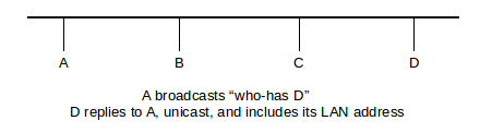
The basic idea of ARP is that the host A sends out a broadcast ARP query or “who-has DIP?” request, which includes A’s own IP and LAN addresses. All hosts on the LAN receive this message. The host for whom the message is intended, D, will recognize that it should reply, and will return an ARP reply or “is-at” message containing DLAN. Because the original request contained ALAN, D’s response can be sent directly to A, that is, unicast.
Additionally, all hosts maintain an ARP cache, consisting of ⟨IP,LAN⟩ address pairs for other hosts on the network. After the exchange above, A has ⟨DIP,DLAN⟩ in its table; anticipating that A will soon send it a packet to which it needs to respond, D also puts ⟨AIP,ALAN⟩ into its cache.
ARP-cache entries eventually expire. The timeout interval used to be on the order of 10 minutes, but linux systems now use a much smaller timeout (~30 seconds observed in 2012). Somewhere along the line, and probably related to this shortened timeout interval, repeat ARP queries about a timed-out entry are first sent unicast, not broadcast, to the previous Ethernet address on record. This cuts down on the total amount of broadcast traffic; LAN broadcasts are, of course, still needed for new hosts. The ARP cache on a linux system can be examined with the command ip -s neigh; the corresponding windows command is arp -a.
The above protocol is sufficient, but there is one further point. When A sends its broadcast “who-has D?” ARP query, all other hosts C check their own cache for an entry for A. If there is such an entry (that is, if AIP is found there), then the value for ALAN is updated with the value taken from the ARP message; if there is no pre-existing entry then no action is taken. This update process serves to avoid stale ARP-cache entries, which can arise is if a host has had its Ethernet card replaced.
7.7.1 ARP Finer Points
Most hosts today implement self-ARP, or gratuitous ARP, on startup (or wakeup): when station A starts up it sends out an ARP query for itself: “who-has A?”. Two things are gained from this: first, all stations that had A in their cache are now updated with A’s most current ALAN address, in case there was a change, and second, if an answer is received, then presumably some other host on the network has the same IP address as A.
Self-ARP is thus the traditional IPv4 mechanism for duplicate address detection. Unfortunately, it does not always work as well as might be hoped; often only a single self-ARP query is sent, and if a reply is received then frequently the only response is to log an error message; the host may even continue using the duplicate address! If the duplicate address was received via DHCP, below, then the host is supposed to notify its DHCP server of the error and request a different IPv4 address.
RFC 5227 has defined an improved mechanism known as Address Conflict Detection, or ACD. A host using ACD sends out three ARP queries for its new IP address, spaced over a few seconds and leaving the ARP field for the sender’s IP address filled with zeroes. This last step means that any other host with that IP address in its cache will ignore the packet, rather than update its cache. If the original host receives no replies, it then sends out two more ARP queries for its new address, this time with the ARP field for the sender’s IP address filled in with the new address; this is the stage at which other hosts on the network will make any necessary cache updates. Finally, ACD requires that hosts that do detect a duplicate address must discontinue using it.
It is also possible for other stations to answer an ARP query on behalf of the actual destination D; this is called proxy ARP. An early common scenario for this was when host C on a LAN had a modem connected to a serial port. In theory a host D dialing in to this modem should be on a different subnet, but that requires allocation of a new subnet. Instead, many sites chose a simpler arrangement. A host that dialed in to C’s serial port might be assigned IP address DIP, from the same subnet as C. C would be configured to route packets to D; that is, packets arriving from the serial line would be forwarded to the LAN interface, and packets sent to CLAN addressed to DIP would be forwarded to D. But we also have to handle ARP, and as D is not actually on the LAN it will not receive broadcast ARP queries. Instead, C would be configured to answer on behalf of D, replying with ⟨DIP,CLAN⟩. This generally worked quite well.
Proxy ARP is also used in Mobile IP, for the so-called “home agent” to intercept traffic addressed to the “home address” of a mobile device and then forward it (eg via tunneling) to that device. See 7.11 Mobile IP.
One delicate aspect of the ARP protocol is that stations are required to respond to a broadcast query. In the absence of proxies this theoretically should work quite well: there should be only one respondent. However, there were anecdotes from the Elder Days of networking when a broadcast ARP query would trigger an avalanche of responses. The protocol-design moral here is that determining who is to respond to a broadcast message should be done with great care. (RFC 1122 section 3.2.2 addresses this same point in the context of responding to broadcast ICMP messages.)
ARP-query implementations also need to include a timeout and some queues, so that queries can be resent if lost and so that a burst of packets does not lead to a burst of queries. A naive ARP algorithm without these might be:
To send a packet to destination DIP, see if DIP is in the ARP cache. If it is, address the packet to DLAN; if not, send an ARP query for D
To see the problem with this approach, imagine that a 32KB packet arrives at the IP layer, to be sent over Ethernet. It will be fragmented into 22 fragments (assuming an Ethernet MTU of 1500 bytes), all sent at once. The naive algorithm above will likely send an ARP query for each of these. What we need instead is something like the following:
To send a packet to destination DIP:If DIP is in the ARP cache, send to DLAN and returnIf not, see if an ARP query for DIP is pending.If it is, put the current packet in a queue for D.If there is no pending ARP query for DIP, start one,again putting the current packet in the (new) queue for D
We also need:
If an ARP query for some CIP times out, resend it (up to a point)If an ARP query for CIP is answered, send off any packets in C’s queue
7.7.2 ARP security
Suppose A wants to log in to secure server S, using a password. How can B (for Bad) impersonate S?
Here is an ARP-based strategy, sometimes known as ARP Spoofing. First, B makes sure the real S is down, either by waiting until scheduled downtime or by launching a denial-of-service attack against S.
When A tries to connect, it will begin with an ARP “who-has S?”. All B has to do is answer, “S is-at B”. There is a trivial way to do this: B simply needs to set its own IP address to that of S.
A will connect, and may be convinced to give its password to B. B now simply responds with something plausible like “backup in progress; try later”, and meanwhile use A’s credentials against the real S.
This works even if the communications channel A uses is encrypted! If A is using the ssh protocol, then A will get a message that the other side’s key has changed (B will present its own ssh key, not S’s). Unfortunately, many users (and even some IT departments) do not recognize this as a serious problem. Some organizations – especially schools and universities – use personal workstations with “frozen” configuration, so that the filesystem is reset to its original state on every reboot. Such systems may be resistant to viruses, but in these environments the user at A will always get a message to the effect that S’s credentials are not known.
7.7.3 ARP Failover
Suppose you have two front-line servers, A and B (B for Backup), and you want B to be able to step in if A freezes. There are a number of ways of achieving this, but one of the simplest is known as ARP Failover. First, we set AIP = BIP, but for the time being B does not use the network so this duplication is not a problem. Then, once B gets the message that A is down, it sends out an ARP query for AIP, including BLAN as the source LAN address. The gateway router, which previously would have had ⟨AIP,ALAN⟩ in its ARP cache, updates this to ⟨AIP,BLAN⟩, and packets that had formerly been sent to A will now go to B. As long as B is trafficking in stateless operations (eg html), B can pick up right where A left off.
7.7.4 Detecting Sniffers
Finally, here is an interesting use of ARP to detect Ethernet password sniffers (generally not quite the issue it once was, due to encryption and switching). To find out if a particular host A is in promiscuous mode, send an ARP “who-has A?” query. Address it not to the broadcast Ethernet address, though, but to some nonexistent Ethernet address.
If promiscuous mode is off, A’s network interface will ignore the packet. If promiscuous mode is on, A’s network interface will pass the ARP request to A itself, which is likely then to answer it.
Alas, linux kernels reject at the ARP-software level ARP queries to physical Ethernet addresses other than their own. However, they do respond to faked Ethernet multicast addresses, such as ff:ff:ff:00:00:00 or ff:ff:ff:ff:ff:fe.
7.8 Dynamic Host Configuration Protocol (DHCP)
DHCP is the most common mechanism by which hosts are assigned their IP addresses. DHCP started as a protocol known as Reverse ARP (RARP), which evolved into BOOTP and then into its present form. It is documented in RFC 2131.
Recall that ARP is based on the idea of someone broadcasting an ARP query for a host, containing the host’s IP address, and the host answering it with its LAN address. DHCP involves a host, at startup, broadcasting a query containing its own LAN address, and having a server reply telling the host what IP address is assigned to it. The DHCP response is likely to contain several other essential startup options as well, including:
- IP address
- subnet mask
- default router
- DNS Server
These four items are a pretty standard minimal network configuration.
The DHCP server has a range of IP addresses to hand out, and maintains a database of which IP address has been assigned to which LAN address. Reservations can either be permanent or dynamic; if the latter, hosts typically renew their DHCP reservation periodically (typically one to several times a day).
7.8.1 DHCP and the Small Office
If you have a large network, with multiple subnets, a certain amount of manual configuration is inevitable. What about, however, a home or small office, with a single line from an ISP? A combination of NAT (1.14 Network Address Translation) and DHCP has made autoconfiguration close to a reality.
The typical home/small-office “router” is in fact a NAT firewall coupled with a switch (usually also coupled with a Wi-Fi access point); we will refer to this as a NAT router. One specially designated port, the external port, connects to the ISP’s line, and uses DHCP to obtain an IP address for that port. The other, internal, ports are connected together by an Ethernet switch; these ports as a group are connected to the external port using NAT translation. If wireless is supported, the wireless side is connected directly to the internal ports.
Isolated from the Internet, the internal ports can thus be assigned an arbitrary non-public IP address block, eg 192.168.0.0/24. The NAT router contains a DCHP server, usually enabled by default, that will hand out IP addresses to everything connecting from the internal side.
Generally this works seamlessly. However, if a second NAT router is also connected to the network (sometimes attempted to extend Wi-Fi range, in lieu of a commercial Wi-Fi repeater), one then has two operating DHCP servers on the same subnet. This often results in chaos, as two different hosts may be assigned the same IP address, or a host’s IP address may suddenly change if it gets a new IP address from the other server. Disabling one of the DHCP servers fixes this.
While omnipresent DHCP servers have made IP autoconfiguration work “out of the box” in many cases, in the era in which IP was designed the need for such servers would have been seen as a significant drawback in terms of expense and reliability. IPv6 has an autoconfiguration strategy (8.13 Stateless Autoconfiguration (SLAAC)) that does not require DHCP, though DHCPv6 may well end up displacing it.
7.8.2 DHCP and Routers
It is often desired, for larger sites, to have only one or two DHCP servers, but to have them support multiple subnets. Classical DHCP relies on broadcast, which isn’t forwarded by routers, and even if it were, the DHCP server would have no way of knowing on what subnet the host in question was actually located.
This is generally addressed by DHCP Relay (sometimes still known by the older name BOOTP Relay). The router (or, sometimes, some other node on the subnet) receives the DHCP broadcast message from a host, and notes the subnet address of the arrival interface. The router then relays the DHCP request, together with this subnet address, to the designated DHCP Server; this relayed message is sent directly (unicast), not broadcast. Because the subnet address is included, the DHCP server can figure out the correct IP address to assign.
This feature has to be specially enabled on the router.
7.9 Internet Control Message Protocol
The Internet Control Message Protocol, or ICMP, is a protocol for sending IP-layer error and status messages. It is, like IP, host-to-host, and so they are never delivered to a specific port, even if they are sent in response to an error related to something sent from that port. In other words, individual UDP and TCP connections do not receive ICMP messages, even when it would be helpful to get them.
Here are the ICMP types, with subtypes listed in the description. The list has been pruned to include only the most common values.
| Type | Description |
|---|---|
| Echo Request | ping queries |
| Echo Reply | ping responses |
| Destination Unreachable | Destination network unreachable |
| Destination host unreachable | |
| Destination port unreachable | |
| Fragmentation required but DF flag set | |
| Network administratively prohibited | |
| Source Quench | Congestion control |
| Redirect Message | Redirect datagram for the network |
| Redirect datagram for the host | |
| Redirect for TOS and network | |
| Redirect for TOS and host | |
| Router Solicitation | Router discovery/selection/solicitation |
| Time Exceeded | TTL expired in transit |
| Fragment reassembly time exceeded | |
| Bad IP Header or Parameter | Pointer indicates the error |
| Missing a required option | |
| Bad length |
ICMP is perhaps best known for Echo Request/Reply, on which the ping tool is based. Ping remains very useful for network troubleshooting: if you can ping a host, then the network is reachable, and any problems are higher up the protocol chain. Unfortunately, ping replies are blocked by default by many firewalls, on the theory that revealing even the existence of computers is a security risk. While this may be an appropriate decision, it does significantly impair the utility of ping. Most routers do still pass ping requests, but some site routers block them.
Source Quench was used to signal that congestion has been encountered. A router that drops a packet due to congestion experience was encouraged to send ICMP Source Quench to the originating host. Generally the TCP layer would handle these appropriately (by reducing the overall sending rate), but UDP applications never receive them. ICMP Source Quench did not quite work out as intended, and was formally deprecated by RFC 6633. (Routers can inform TCP connections of impending congestion by using the ECN bits.)
The Destination Unreachable type has a large number of subtypes:
- Network unreachable: some router had no entry for forwarding the packet, and no default route
- Host unreachable: the packet reached a router that was on the same LAN as the host, but the host failed to respond to ARP queries
- Port unreachable: the packet was sent to a UDP port on a given host, but that port was not open. TCP, on the other hand, deals with this situation by replying to the connecting endpoint with a reset packet. Unfortunately, the UDP Port Unreachable message is sent to the host, not to the application on that host that sent the undeliverable packet, and so is close to useless as a practical way for applications to be informed when packets cannot be delivered.
- Fragmentation required but DF flag set: a packet arrived at a router and was too big to be forwarded without fragmentation. However, the Don’t Fragment bit in the IP header was set, forbidding fragmentation. Later we will see how TCP uses this option as part of Path MTU Discovery, the process of finding the largest packet we can send to a specific destination without fragmentation. The basic idea is that we set the DF bit on some of the packets we send; if we get back this message, that packet was too big.
- Administratively Prohibited: this is sent by a router that knows it can reach the network in question, but has configured to drop the packet and send back Administratively Prohibited messages. A router can also be configured to blackhole messages: to drop the packet and send back nothing.
7.9.1 Traceroute and Time Exceeded
The traceroute program uses ICMP Time Exceeded messages. A packet is sent to the destination (often UDP to an unused port), with the TTL set to 1. The first router the packet reaches decrements the TTL to 0, drops it, and returns an ICMP Time Exceeded message. The sender now knows the first router on the chain. The second packet is sent with TTL set to 2, and the second router on the path will be the one to return ICMP Time Exceeded. This continues until finally the remote host returns something, likely ICMP Port Unreachable.
Many routers no longer respond with ICMP Time Exceeded messages when they drop packets. For the distance value corresponding to such a router, traceroute reports ***.
Traceroute assumes the path does not change. This is not always the case, although in practice it is seldom an issue.
Traceroute to a nonexistent site works up to the point when the packet reaches the Internet “backbone”: the first router which does not have a default route. At that point the packet is not routed further (and an ICMP Destination Network Unreachable should be returned).
7.9.2 Redirects
Most non-router hosts start up with an IP forwarding table consisting of a single (default) router, discovered along with their IP address through DHCP. ICMP Redirect messages help hosts learn of other useful routers. Here is a classic example:
A is configured so that its default router is R1. It addresses a packet to B, and sends it to R1. R1 receives the packet, and forwards it to R2. However, R1 also notices that R2 and A are on the same network, and so A could have sent the packet to R2 directly. So R1 sends an appropriate ICMP redirect message to A (“Redirect Datagram for the Network”), and A adds a route to B via R2 to its own forwarding table.
7.9.3 Router Solicitation
These ICMP messages are used by some router protocols to identify immediate neighbors. When we look at routing-update algorithms, below, these are where the process starts.
7.10 Unnumbered Interfaces
We mentioned in 1.10 IP - Internet Protocol and 7.2 Interfaces that some devices allow the use of point-to-point IP links without assigning IP addresses to the interfaces at the ends of the link. Such IP interfaces are referred to as unnumbered; they generally make sense only on routers. It is a firm requirement that the node (ie router) at each endpoint of such a link has at least one other interface that does have an IP address; otherwise, the node in question would be anonymous.
The diagram below shows a link L joining routers R1 and R2, which are connected to subnets 200.0.0.0/24 and 201.1.1.0/24 respectively. The endpoint interfaces of L, both labeled link0, are unnumbered.
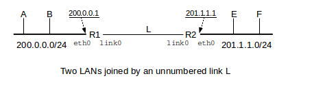
The endpoints of L could always be assigned private IP addresses (7.3 Special Addresses), such as 10.0.0.1 and 10.0.0.2. To do this we would need to create a subnet; because the host bits cannot be all 0’s or all 1’s, the minimum subnet size is four (eg 10.0.0.0/30). Furthermore, the routing protocols to be introduced in 9 Routing-Update Algorithms will distribute information about the subnet throughout the organization or “routing domain”, meaning care must be taken to ensure that each link’s subnet is unique. Use of unnumbered links avoids this.
If R1 were to originate a packet to be sent to (or forwarded via) R2, the standard strategy is for it to treat its link0 interface as if it shared the IP address of its Ethernet interface eth0, that is, 200.0.0.1; R2 would do likewise. This still leaves R1 and R2 violating the IP local-delivery rule of 7.5 The Classless IP Delivery Algorithm; R1 is expected to deliver packets via local delivery to 201.1.1.1 but has no interface that is assigned an IP address on the destination subnet 201.1.1.0/24. The necessary dispensation, however, is granted by RFC 1812. All that is necessary by way of configuration is that R1 be told R2 is a directly connected neighbor reachable via its link0 interface. On linux systems this might be done with the ip route command on R1 as follows:
ip route add 201.1.1.1 dev link0
Because L is a point-to-point link, there is no destination LAN address and thus no ARP query.
7.11 Mobile IP
In the original IPv4 model, there was a strong if implicit assumption that each IP host would stay put. One role of an IP address is simply as a unique endpoint identifier, but another role is as a locator: some prefix of the address (eg the network part, in the class-A/B/C strategy, or the provider prefix) represents something about where the host is physically located. Thus, if a host moves far enough, it may need a new address.
When laptops are moved from site to site, it is common for them to receive a new IP address at each location, eg via DHCP as the laptop connects to the local Wi-Fi. But what if we wish to support devices like smartphones that may remain active and communicating while moving for thousands of miles? Changing IP addresses requires changing TCP connections; life (and application development) might be simpler if a device had a single, unchanging IP address.
One option, commonly used with smartphones connected to some so-called “3G” networks, is to treat the phone’s data network as a giant wireless LAN. The phone’s IP address need not change as it moves within this LAN, and it is up to the phone provider to figure out how to manage LAN-level routing, much as is done in 3.3.5 Wi-Fi Roaming.
But Mobile IP is another option, documented in RFC 5944. In this scheme, a mobile host has a permanent home address and, while roaming about, will also have a temporary care-of address, which changes from place to place. The care-of address might be, for example, an IP address assigned by a local Wi-Fi network, and which in the absence of Mobile IP would be the IP address for the mobile host. (This kind of care-of address is known as “co-located”; the care-of address can also be associated with some other device – known as a foreign agent – in the vicinity of the mobile host.) The goal of Mobile IP is to make sure that the mobile host is always reachable via its home address.
To maintain connectivity to the home address, a Mobile IP host needs to have a home agent back on the home network; the job of the home agent is to maintain an IP tunnel that always connects to the device’s current care-of address. Packets arriving at the home network addressed to the home address will be forwarded to the mobile device over this tunnel by the home agent. Similarly, if the mobile device wishes to send packets from its home address – that is, with the home address as IP source address – it can use the tunnel to forward the packet to the home agent.
The home agent may use proxy ARP (7.7.1 ARP Finer Points) to declare itself to be the appropriate destination on the home LAN for packets addressed to the home (IP) address; it is then straightforward for the home agent to forward the packets.
An agent discovery process is used for the mobile host to decide whether it is mobile or not; if it is, it then needs to notify its home agent of its current care-of address.
There are several forms of packet encapsulation that can be used for Mobile IP tunneling, but the default one is IP-in-IP encapsulation, defined in RFC 2003. In this process, the entire original IP packet (with header addressed to the home address) is used as data for a new IP packet, with a new IP header (the “outer” header) addressed to the care-of address.
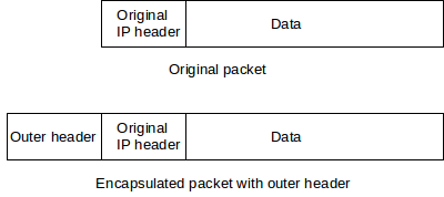
A special value in the IP-header Protocol field indicates that IP-in-IP tunneling was used, so the receiver knows to forward the packet on using the information in the inner header. The MTU of the tunnel will be the original MTU of the path to the care-of address, minus the size of the outer header.
7.12 Epilog
At this point we have concluded the basic mechanics of IPv4. Still to come is a discussion of how IP routers build their forwarding tables. This turns out to be a complex topic, divided into routing within single organizations and ISPs – 9 Routing-Update Algorithms – and routing between organizations – 10 Large-Scale IP Routing.
But before that, in the next chapter, we compare IPv4 with IPv6, now twenty years old but still seeing very limited adoption. The biggest issue fixed by IPv6 is IPv4’s lack of address space, but there are also several other less dramatic improvements.
7.13 Exercises
1. Suppose an Ethernet packet represents a TCP acknowledgment; that is, the packet contains an IP header and a 20-byte TCP header but nothing else. Is the IP packet here smaller than the Ethernet minimum-packet size, and, if so, by how much?
2. How can a receiving host tell if an arriving IP packet is unfragmented?
3. How long will it take the IDENT field of the IP header to wrap around, if the sender host A sends a stream of packets to host B as fast as possible? Assume the packet size is 1500 bytes and the bandwidth is 600 Mbps.
4. The following diagram has routers A, B, C, D and E; E is the “border router” connecting the site to the Internet. All router-to-router connections are via Ethernet-LAN /24 subnets with addresses of the form 200.0.x. Give forwarding tables for each of A, B, C and D. Each table should include each of the listed subnets and also a default entry that routes traffic toward router E.
200.0.5────A────200.0.6────B────200.0.7────D────200.0.8────E────Internet
                           │
                       200.0.9
                           │
                           C
                           │
                       200.0.10
5. (This exercise is an attempt at modeling Internet-2 routing.) Suppose sites S1 ... Sn each have a single connection to the standard Internet, and each site Si has a single IP address block Ai. Each site’s connection to the Internet is through a single router Ri; each Ri‘s default route points towards the standard Internet. The sites also maintain a separate, higher-speed network among themselves; each site has a single link to this separate network, also through Ri. Describe what the forwarding tables on each Ri will have to look like so that traffic from one Si to another will always use the separate higher-speed network.
6. For each IP network prefix given (with length), identify which of the subsequent IP addresses are part of the same subnet.
7. Suppose that the subnet bits below for the following five subnets A-E all come from the beginning of the fourth byte of the IP address; that is, these are subnets of a /24 block.
- A: 00
- B: 01
- C: 110
- D: 111
- E: 1010
8. In Section 4.6 it was stated that, in newer implementations, “repeat ARP queries about a timed out entry are first sent unicast”. Why is this likely to succeed most of the time? Under what conditions would the unicast query fail?
9. Suppose A broadcasts an ARP query “who-has B?”, receives B’s response, and proceeds to send B a regular IP packet. If B now wishes to reply, is it likely that A will already be present in B’s ARP cache? Why?
10. Suppose A broadcasts an ARP request “who-has B”, but inadvertently lists the physical address of another machine C instead of its own (that is, A’s ARP query has IPsrc = A, but LANsrc = C). What will happen? Will A receive a reply? Will any other hosts on the LAN be able to send to A? What entries will be made in the ARP caches on A, B and C?